- TOP
- Ball Reducer Line-up
- Reinformed Ball Reducer SFP series
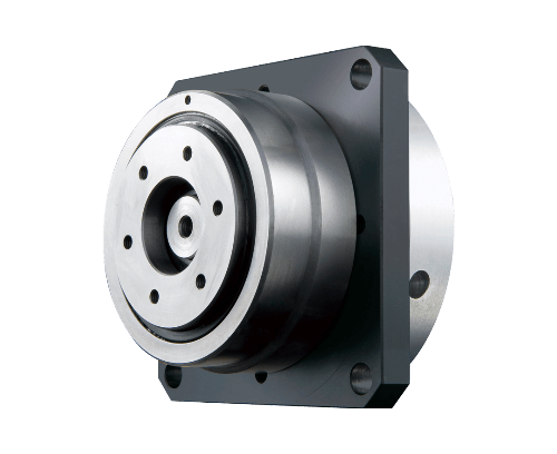
Reinformed Ball Reducer SFP series
A Ball Reducer featuring increased allowable torque due to its improved cycloid curve in the torque transmission section, its allowable radial load has also been enhanced by using three-point support for its output shaft bearing.

Highlights
Improved Load Capacity
Boasts improved allowable radial load of the output shaft and enhanced rigidity, with every component upgraded based on the BR Series.
Zero-Backlash
Uses a steel ball in the deceleration mechanism instead of a gear. Eliminates backlash and enables prevision feeding and high-precision positioning through constant rolling contact via preload.
Compact & Simple
Has a reduction mechanism and input/output bearings built into its housing for compactness and ease of installation.
Motor Attachment Standardization
The SFP Series has standardized motor attachments for servo motors of various manufacturers, allowing the motor to be immediately installed after purchase.
Maintenance-free
Its grease-filled reducer can be used without lubrication for its entire rated life. Also has no mounting position restrictions.
High Efficiency
Its transmission mechanism uses a large number of steel balls to achieve a high-efficiency drive. The rolling contact of the balls is similar to that of a ball screw, allowing extremely light operation and maximized capacity of any motor.
Model
Roller Pinion
| SFP | 1 |
|---|---|
| 70 | 2 |
| S | 3 |
| C | 4 |
| A | |
| 10 | 5 |
| A01 | 6 |
| 08 | 7 |
| 16 | 8 |
| 0 | |
| 0 | |
| A | 9 |
| 0 | 10 |
| 1.Product Name | SFP series |
|---|---|
| 2.Frame number | 70,85,100,125 |
| 3.Output shaft shape | S:Shaft output |
| 4.Input shaft shape | C:Clamp |
| 5.Reduction ratio | 8 (70 only), 10, 20, 30, 40, 50 (125 only) |
| 6.Motor mounting code | Please refer to the dimensional drawing or the motor and reducer compatibility chart. |
| 7.Input shaft hole diameter | Please refer to the specification table or dimensional drawing. |
| 8.Output shaft diameter | 16(70 only),20(85 only),25(100 only),30(125 only) |
| 9.Output shaft option | A:Standard B:With keyway C:Tip tap D:With keyway + Tip tap |
| 10.Mounting plate | F:Available 0:None |
Specifications
| Reduction ratio | |
|---|---|
| Rotation direction(Rotation direction of output shaft correlated to input shaft) | |
| Allowable rated torque | N・m |
| Acceleration peak torque | N・m |
| Maximum instantaneous torque | N・m |
| Allowable radial load at output shaft *1 | N |
| Allowable thrust load at output shaft *1 | N |
| Allowable average number of input revolutions | rpm |
| Max input rpm | rpm |
| Inertia moment converted to input shaft | x10-4 kg・m2 |
| Recommendable motor capacity | W |
| Input shaft hole diameter | mm |
| Outline Drawing | |
| 8 | 10 | 20 | 30 | 10 | 20 | 30 | 40 | 10 | 20 | 30 | 40 | 10 | 20 | 30 | 40 | 50 |
| Reverse | Forward | Reverse | Forward | Reverse | Forward | Reverse | Forward | |||||||||
| 10 | 11 | 12 | 12.8 | 25.5 | 28.4 | 26.2 | 26 | 48.8 | 56 | 56 | 56 | 90 | 96.5 | 96.5 | 98.8 | 99.2 |
| 20 | 21.2 | 22 | 22.6 | 42 | 48.3 | 44.6 | 44.2 | 78 | 89.4 | 95.2 | 95.2 | 155 | 168.9 | 168.9 | 172.9 | 173.6 |
| 40 | 70 | 85 | 130 | 160 | 240 | 270 | ||||||||||
| 500 | 1000 | 1500 | 2000 | |||||||||||||
| 200 | 400 | 600 | 1000 | |||||||||||||
| 3000 | 3000 | 2000 | 2000 | |||||||||||||
| 4500 | 4500 | 4000 | 4000 | |||||||||||||
| 0.149 | 0.149 | 0.159 | 0.161 | 0.484 | 0.431 | 0.414 | 0.406 | 1.58 | 1.43 | 1.38 | 1.36 | 3.45 | 2.98 | 2.86 | 2.81 | 2.78 |
| 200 | 200 | 100 | 100 | 400 | 200 | 200 | 100 | 750 | 400 | 400 | 200 | 1500 | 750 | 750 | 400 | 400 |
| 14 | 14 | 19 | 24 | |||||||||||||
| 11 | 11 | 16 | 22 | |||||||||||||
| 8 | 8 | 14 | 19 | |||||||||||||
| – | – | 11 | 16 | |||||||||||||
| – | – | – | 14 | |||||||||||||
*1 This allowable radial load value is realized when the load positioned in the axial direction is the figure at top of shaft.


